New SV07+ setup - using the ‘gear’ levelling nuts - levelled, un-tilted, mesh probed, z-offset printing good first layers.
However, If I print a full-sheet first layer test, the right side is right at the edge of the build sheet, but the left side is about 20mm in from the left edge.
Is there some setting (or physical process) to adjust this to be somewhat close to center?
The umbilical cable is behind left post - zip-tied with a 3d printed bracket model I found online. It’s not pinching or restricting the carriage movement. Based on your suggestion, I tried:
Turning the printer off and manually moving left. It did seem to move further left than I’d seen it go while homing before. Powering on, and homing, it went all the way left (to where the nozzle is just slightly off the left edge of the build plate - and jogging it to the extreme right, where the nozzle is just off the right edge - appears symmetrical).
I looked up about the motor feedback homing mechanism vs stop switches - so I think I understand how it’s supposed to work now. I have not adjusted the X tension knob at all - because the sound of the belt sounded good from the start (compared to youtube setup examples).
When I run the first layer test print again, it moves all the way left while homing the axes during setup - but still prints offset to the right - leaving about a couple of centimeters unused on the left of the build plate. The rough spot is because of a priming line - the first thing that gets printed by the head - from about middle of Y to near the front of build plate that overlapped the left ‘frame’ of the first layer test and only happened this one time - I’m not worried about that, and I don’t think it’s related to the left-right not-centered issue.
stepper_x:
postition_endstop was originally -13
position_min was originally -13
I subtracted 8 after measuring (total of 16mm outside the printed area - divide by two for centering) - and tried -21 for both - but that put the print even further off the right edge.
With a number near to zero, I figured the left end of the X-axis would be low - and higher numbers to the right. However it seems to be the opposite - changing to -5 for both values, I now get the attached image. z offset still needs refining, but otherwise looks plenty good to me.
Continuing on this thread since this may be a natural problem follow-on for other people that make the change I made to the stepper_x settings.
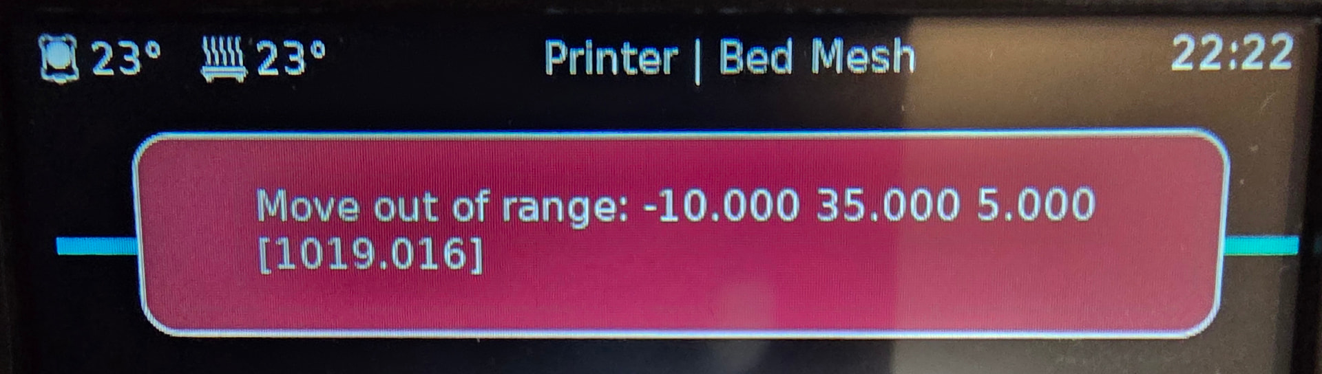
I figured I should re-calibrate and re-mesh check the bed, since the bed ‘moved’ by changing those settings. Levelling went fine - but mesh won’t run now. I expect there’s some other setting I have to change to counteract the postion_endstop or position_min change.
Since it’s trying to move to -10 X - and -5 is now my minimum - that’s out of range, but I’m not sure what to adjust to make the mesh check process happy.
Before I saw your response, I found a different answer via a reddit thread:
In that thread, the poster says that after changing stepper_x→position_endstop (he increased it by 8), he also couldn’t run the mesh, and had to change [probe]→x_offset, decreasing it by 7.
Since his change was similar to mine (increasing position_endstop by 8, as I did) - I went for the same -7 to x_offset. After that I was able to run the mesh successfully.
I’ll change it back and try your suggestion instead and see if I notice a difference between the two approaches.
I don’t think the Klipper documentation does a good job of explaining when different coordinate systems apply in interpreting the values. For example, on Bed Mesh - Klipper documentation -
The lead-in says 250x220, but then says [35,6] → [240,198] without saying where those numbers from from. the 24mm and 5mm offsets mentioned don’t explain it either.
Changing the probe offset will result in klipper probing in the wrong spot. The offset is there so that when probing the probe is at the same spot as the nozzle is going to be when printing.
8mm away is probably okay but it is easy enough to change the grid size and keep the offset correct.
EDIT: I think the documentation is wrong. I think you layout the grid you WANT to probe and klipper automatically offsets the position it probes at.