I recently made the jump to Mainline to facilitate installation of an Eddy Duo. Things went relatively well, but I need some input on an issue causing a bad first layer. When the machine runs QGL, my Z1 is reporting a deviation of roughly 3mm. The software does attempt to compensate, but I’m having an issue where where my first layer has a 0.5mm or greater variance in as little as 100mm from side to side that the machine is unable to correct.
I have a screenshot of the console output from roughly 20 minutes ago, but the output can be duplicated at will.
What I need is a direction to start from and steps to take. I feel like there is an underlying issue that existed before the software and hardware changes.
Realistically, all I have done at this point is played with Z offset and different bed plates. I have not straight edged the bed and have not investigated the gantry system.
Something this printer has done since nearly new, when it drops the nozzle to knock off the blob near 0,0, one of the belts chirps. I’ve been meaning to get a video of this.
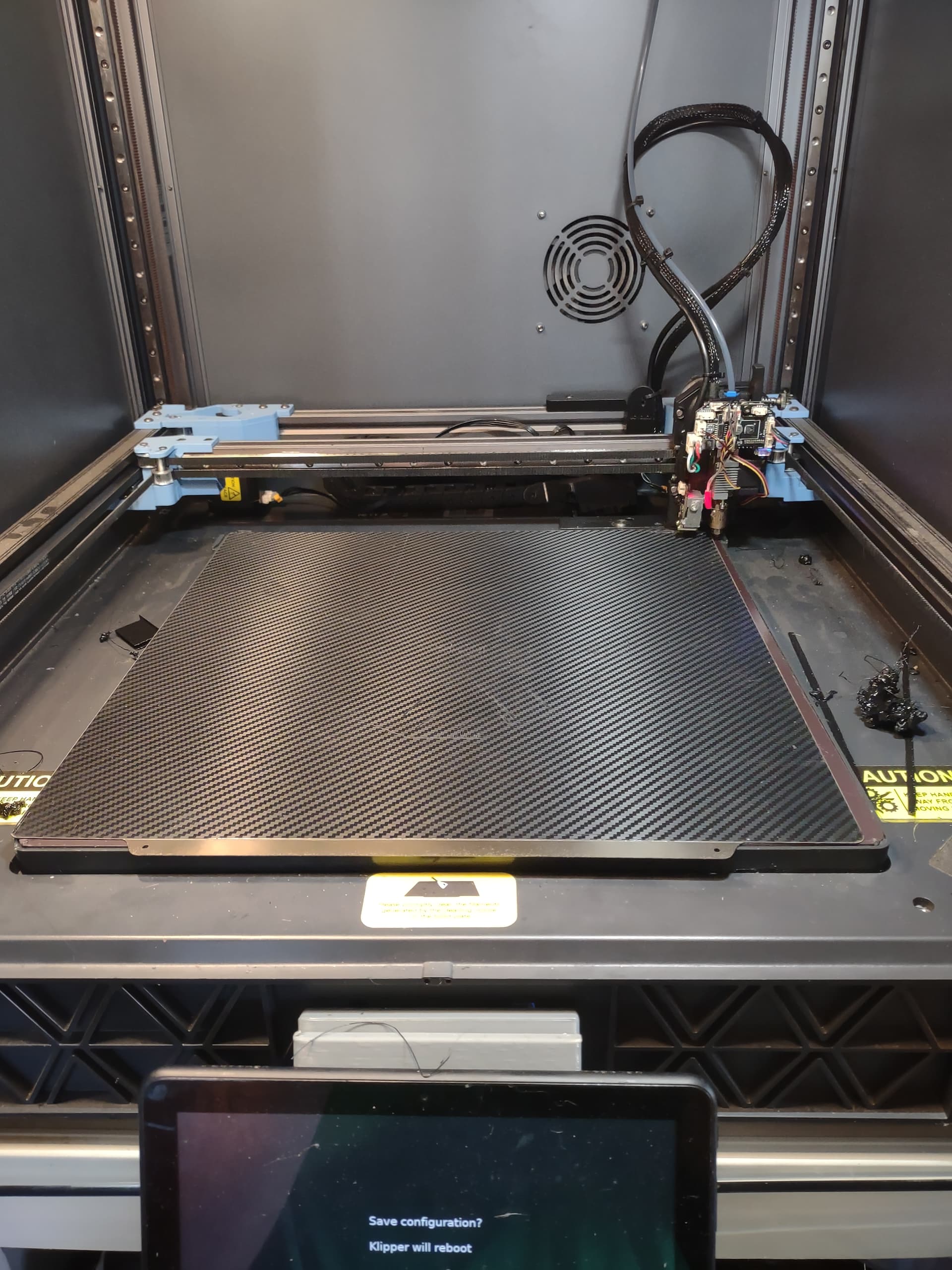
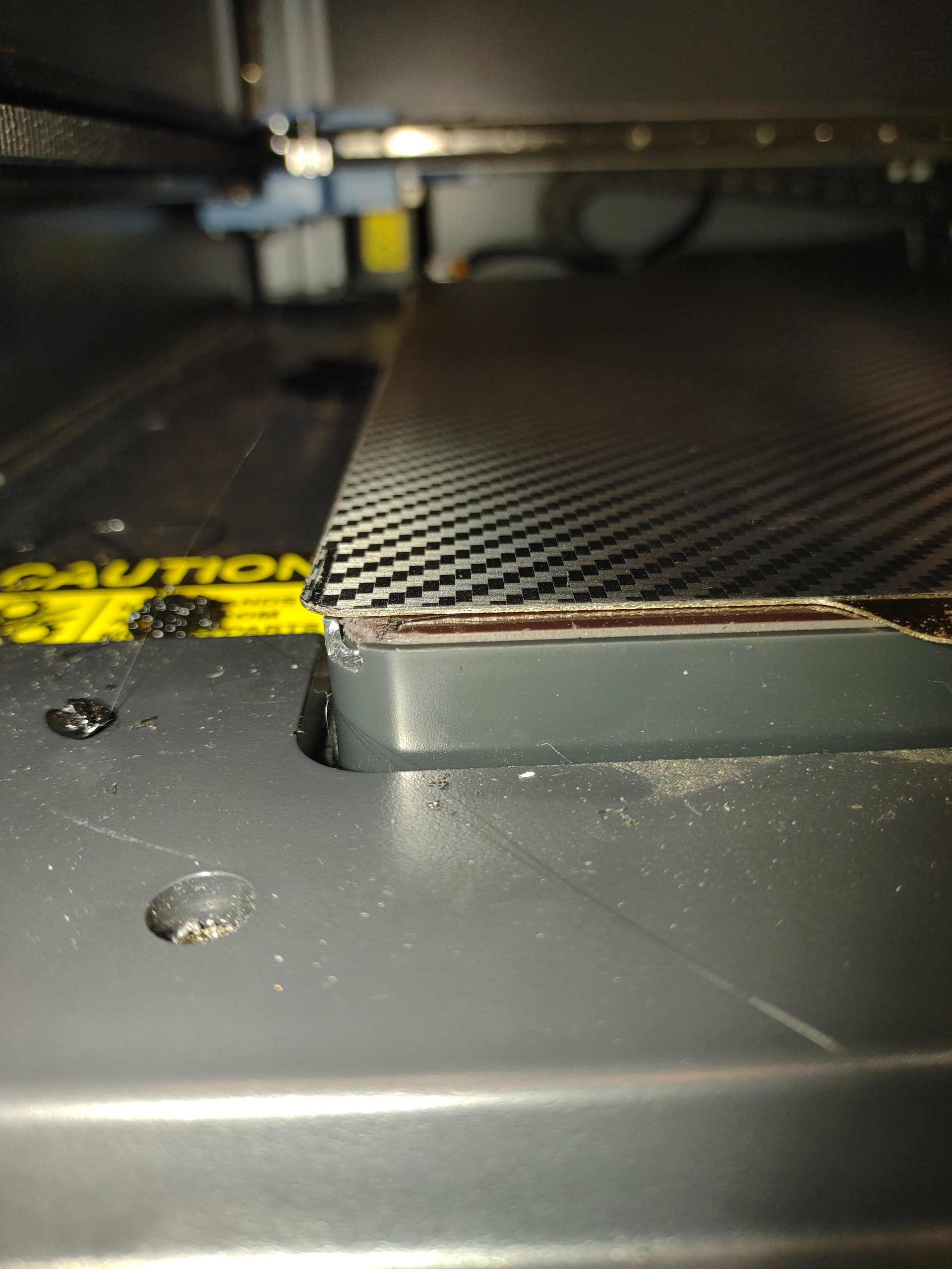
I may have been a bit quick to post. The aftermarket bed plate is small enough that the Eddy probe is actually scanning the edge of the bed. I put the sovol plate back on and got better results from the QGL and mesh.
I managed to kick off a print by shifting the part footprint to the rear of the bed. I suppose a teardown is in order to find out how to correct the bed level condition. I see in the other thread that the idea of a glass plate was mentioned.
I will check that. As a temporary solution, I’m going to try to get the magnetic layer flat as described on the R3men graphite bed webpage. I think that will be a work around unit I’m ready to throw more dollars at this machine.
I read that. I will be migrating to a graphite bed eventually and may devise a tripodal mount of some sort.
In the interim, I found the issue at hand. I actually had time to get down at eye level and watch the first layer print. I found that the rear Z belts had plastic debris down inside the pulley structure. I am tall enough and the printer is just low enough that when I stand in front of the machine, my view of the belts below and behind the motors is obstructed. During the QGL, I noticed the belts kicking out of plane. The parts were large enough to pulled into the pulley and then be spit out repeatedly.
Ideally the bed should have 3 distinct mount points.
single degree of freedom (yaw)
2 degrees of freedom (linear through point 1 and yaw
3 degrees of freedom (X,Y, and yaw)
However with the small magnitude of the frame flex I feel that the standoffs (if not overtightened) will be flexible enough such that the forces transferred to the bed are not going to be strong enough to (measurably) flex the bed.
I don’t have a SV08 to test my theory so I could be wrong.
There is a post in that other thread where someone has used a short linear rail and a slip plate. Personally I wouldn’t spend the time and money without testing the simpler design first.
After reading the other thread, I immediately conceived of ball bearings in concave pads. I ran the idea by a friend and he replied with Oldham joints. These seem like they would be relatively easy to retrofit using the existing mounting locations.
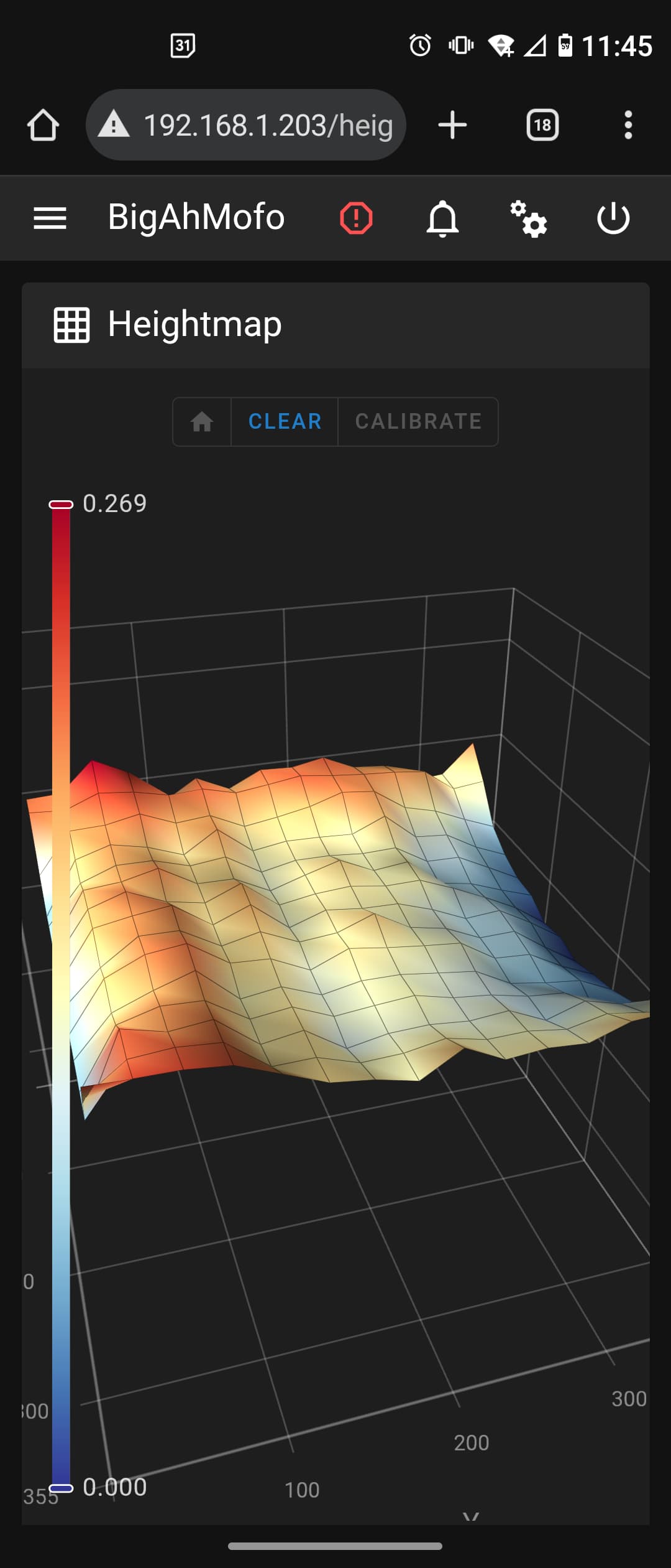
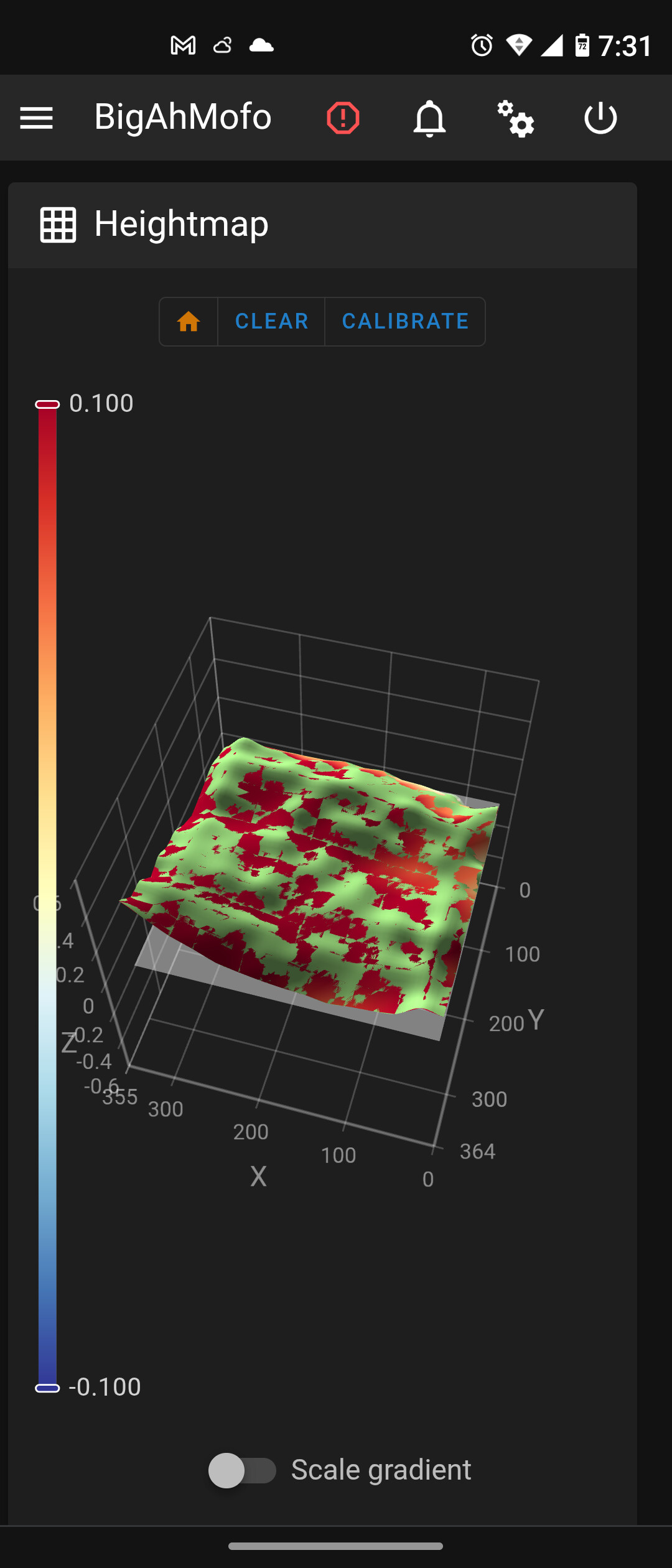
I believe I have another problem entirely. After reviewing my first layer and the way multiple prints have failed, it became apparent that the mesh mesh X axis is inverted.
I confirmed this by shifting the build plate off the bed slightly and running the QGL and bed mesh. The result: The intensionally high point appears at X 350ish rather than X 0
I don’t know how to correct this, or what the root cause is yet.
There is that chance. I do know that the stickers for the motors do not correlate to the Z motor positions.
Z0 probe point does not correlate to Z1 motor.
I knew you would mention the number of points. They can’t cause a taco if they have no rigid point to act against.
I ordered to of those oldham joints to see them first hand. I wonder if I should use the existing screw holes in the joints or fab 8mm dowles to engage the through holes in the joints halves.
Your couplings ARE rigid in the Z axis. They can push up or pull down on the plate. If you are planning on leaving the grub screws loose and allow the plate to float then they have 4 degrees of freedom and only constrain motion in pitch and roll. I don’t expect the frame to twist enough to warp the plate in such a configuration but if they aren’t active in the Z axis why bother?
The original build plate is not on the edge plastic trim but in between the edges, I think that explains why that edge is higher than the rest of the plate.
I believe you missed the fact that I did that intensionally for test purpose only, as the plate in the photo is roughly 10mm narrower that the bed overall.
[quote] Your couplings ARE rigid in the Z axis. They can push up or pull down on the plate. If you are planning on leaving the grub screws loose and allow the plate to float then they have 4 degrees of freedom and only constrain motion in pitch and roll. I don’t expect the frame to twist enough to warp the plate in such a configuration but if they aren’t active in the Z axis why bother?[/quote]
That was the point in selecting the joints with the unthreaded holes and utilizing a dowel, so that Z is not constrained.
It may not work, I may never install them.
The Z motors are wired correctly and are defined correctly.
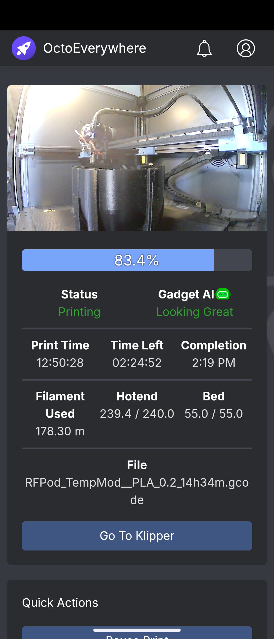
I reduced the bounds of the mesh by 10mm on each axis and have gotten favorable (workable) results. I made it 7 hours into a print and appear to have been bitten by filament inconsistency. The first layer and adhesion seem to be corrected.
With that verification, I tend to believe lapping the magnetic surface is the only short term fix left on the table. I only have one large footprint part to print (the reason I bought the machine) and it’s printed on a raft.