Z-Offset is not saved

While the eddie current sensor is real good, I cannot get a perfect first layer on the full bed surface, unless I adjust Z-Offset. Doing so, my first layer is absolutely top notch, on all 150x150mm.

But whatever I do, either via Mainsail (Klipper WebUI) by clicking on the SAVE and SAVE_CONFIG buttons, or via the small display of the Zero via End-Save Z-Offset, doesn’t get stored in the EEPROM / doesn’t survive a power cycle or a reboot.

Is there any other way to save the Z-Offset in EEPROM, so I don’t have to input it manually every time?

Thanks!

Which version of the OS are you running? Sovol completely changed how the printer locates Z0 in version 1.4.x

@sovol3d where is the documentation for the z_offset_calibration routine used by the Zero?

[z_offset_calibration]
non_contact_probe: probe_eddy_current eddy
contact_probe: probe_eddy_current eddy
center_xy_position: 96,76.2
endstop_xy_position: 96,76.2                        
z_hop: 5                       
z_hop_speed: 15
internal_endstop_offset: -0.20 

This seems to be a Sovol specific function as there is no mention of it in the Klipper documentation.

It seems that the hard coded internal_endstop_offset of -.20 may not be the optimum value for all machines with all materials. I assume that the offset is SUBTRACTED from the value generated during the “tap” so that HIGHER offset values (I.E -.10) would result in the final Z0 value being closer to the bed.

1.4.1, I’m a but wary of installing 1.4.2 due to the pressure sensor being (supposedly) ignored in/from that version.

@cardoc, thank you, yes I’ve seen printer.cfg but it’s not really clear, I have experimented a bit but the values at the bottom get overwritten, etc… and I looked for a possibly better / more straight solution.

@Sovol3D I would prefer to do something which is reflected in the Z-Offset displayed (both in the Zero display and in Mainsail), as to be aware that I have e.g. -0.08 offset, and not forget it.
In other words, simply save / make permanent the Z-Offset I’ve set.

Not being able to adjust the Z offset calibration on the Zero seemed odd to me. At first I assumed I was missing something. I found the Z offset in Mainsail. It was a bit different than I was accustomed to on a couple of other Klipper printers. I was able to adjust the Z offset and then save and restart the Zero. The first layer adhesion seemed to improve after setting -0.10 mm for the Z offset and doing the save and restart, as if the internal Z offset was changed, but it seemed sketchy and I’m not sure if I actually changed the Z offset in a manner that persists after a reboot. If it works, it’s less assuring than other Klipper interfaces.

One thing that definitely helped with a perfect first layer was slowing the first layer speed to 50 mm/s. The Zero is sold based on impressively fast speed and acceleration but I believe all of the stock filament profiles are too fast. For strong prints that look as good as possible, I slowed the speed and acceleration to more reasonable values.

1 Like

I am having the same issues and it’s very frustrating. The Z offset will not save after doing a Save_config, and my printer is constantly starting prints too low.

Even doing a probe_calibrate ends up with the same results after doing a save_config. There is something overwriting the set Z offset, either after every print or every time the machine shuts down.

1 Like

1.4.1 no longer uses the pressure sensor. The section of the printer.cfg I posted above is from 1.4.1. Sovol doesn’t even define a pin for the pressure sensor output much less use it for finding Z0

It was 1.4.1 yesterday on WIKI…
But my Zero updated to 1.4.7 yesterday, so i don’t have any answers.

The changelog is incorrect.

I downloaded SV08 zero_Update_Package-04-07-1.4.1.deb from Sovol, opened it with 7zip and drilled down to Find /home/sovol/printer_data/config/printer.cfg

I’ve attached that file below but I assure you it does NOT use the pressure sensor
printer.cfg (9.3 KB)

@sovol3d Could you please add the version number as a comment in your printer.cfg files?

1 Like

Based on comparing the firmware packages so totally unofficial information:

1.3.8 → 1.4.0 removes the pressure sensor from being used, rewrites the z offset routine and makes the chamber fan temperature controlled + plenty of other smaller changes, contains also new klipper firmware
1.4.0 → 1.4.1 changes the firmware flashing procedure, nothing else
1.4.1 → 1.4.2 contains only a mainsail change
1.4.3 - 1.4.5 haven’t been released to the public as far as I can tell
1.4.2 → 1.4.6 upgrades wifi driver in a way that the previous version can’t be rolled back with a firmware downgrade, internal_endstop_offset gets modified from -0.20 to -0.10, new wifi service gets installed but nothing uses it, some configuration changes to the unreleased chamber heater, new logic to not flash the firmware unless it has been changed
1.4.6 → 1.4.7 changes internal_endstop_offset back from -0.10 to -0.20, no other changes, possibly suggesting the offset change in 1.4.6 was a mistake or caused issues

The logic in all firmwares for z-offset has been to calibrate it at the beginning of each print. It’s not saved at all. internal_endstop_offset can be used to adjust the offset but if the automatic calibration starts drifting between prints then there’s no option available for locking the value down.

Note that z_offset under “probe_eddy_current eddy” will likely also contribute to the used z-offset if changed.

Also worth noting that the resonance tester frequency range is still only 35-45 Hz for some reason when the peak is around 55-60 Hz so the tester isn’t going to produce optimal results unless the range is first adjusted to something wider, like 20-80 Hz. This is however unrelated to the z-offset behaviour.

3 Likes

Also worth noting last commit at gitgub was on Mar 25, 2025. (1.4.1?) and most folders other than /home/sovol are empty

Still no “support page” at sovol3d.com.

Only version of firmware at the wiki is 1.4.1 despite the (incorrect) changelog at the bottom of the page.

1 Like

Thanks for your suggestion. I have gave feedback it to the technician

1 Like

I tried printing a small PETG part last night. PETG has always printed well on my Zero other than one bad clog in the heat break that was caused by the chamber being too hot, but there were bed adhesion problems with a small blob stuck to the nozzle and nothing stuck to the 80 C bed… three times. I changed back to TPU. It takes half an hour for the bed to cool to 35 C if I forget to manually turn on the auxiliary cooling fan before starting the print job. Once Klipper is in the startup routine, it does all of the startup procedures sequentially and ignores all external commands, such as turning on the fan.

The TPU part wasn’t sticking to the bed either. I used the Z offset in Mainsail to lower the nozzle 0.05 mm and it printed the small part a few times, with the fast full bed Eddy scan each time, but I have no idea when the Zero will decide to lose its Z offset again.

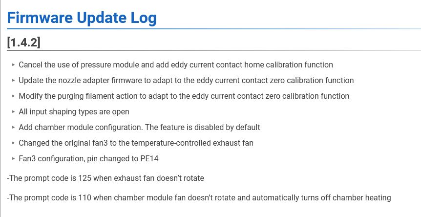
I just upgraded the firmware from 1.4.2 (20250425) to 1.4.7 (20250520) and then did the full calibration from the front panel (Eddy and input shaping) and it rebooted. I’ll see if that helps with the non-persistent Z offset, but based on this thread, I’m not hopeful.

Here are the calibration results. It looks like the excitation of X and Y are 35 to 45 Hz in 1 Hz increments but it’s measuring the harmonic response over a wider frequency.

11:28 PM
The SAVE_CONFIG command will update the printer config file
with these parameters and restart the printer.
11:28 PM
Shaper calibration data written to /tmp/calibration_data_y_20250526_032800.csv file
11:28 PM
shaper_type_y:zv shaper_freq_y:43.400 damping_ratio_y:0.001000
11:28 PM
shaper_type_x:mzv shaper_freq_x:40.200 damping_ratio_x:0.001000
11:28 PM
Recommended shaper_type_y = zv, shaper_freq_y = 43.4 Hz
11:28 PM
To avoid too much smoothing with ‘3hump_ei’, suggested max_accel <= 4700 mm/sec^2
11:28 PM
Fitted shaper ‘3hump_ei’ frequency = 80.2 Hz (vibrations = 0.0%, smoothing ~= 0.127)
11:28 PM
To avoid too much smoothing with ‘2hump_ei’, suggested max_accel <= 5000 mm/sec^2
11:28 PM
Fitted shaper ‘2hump_ei’ frequency = 67.2 Hz (vibrations = 0.0%, smoothing ~= 0.119)
11:28 PM
To avoid too much smoothing with ‘ei’, suggested max_accel <= 5400 mm/sec^2
11:28 PM
Fitted shaper ‘ei’ frequency = 54.0 Hz (vibrations = 0.0%, smoothing ~= 0.110)
11:28 PM
To avoid too much smoothing with ‘mzv’, suggested max_accel <= 6000 mm/sec^2
11:28 PM
Fitted shaper ‘mzv’ frequency = 45.2 Hz (vibrations = 0.0%, smoothing ~= 0.100)
11:28 PM
To avoid too much smoothing with ‘zv’, suggested max_accel <= 7300 mm/sec^2
11:28 PM
Fitted shaper ‘zv’ frequency = 43.4 Hz (vibrations = 0.6%, smoothing ~= 0.087)
11:28 PM
Calculating the best input shaper parameters for y axis
11:28 PM
Shaper calibration data written to /tmp/calibration_data_x_20250526_032800.csv file
11:28 PM
shaper_type_y:mzv shaper_freq_y:40.000 damping_ratio_y:0.001000
11:28 PM
shaper_type_x:mzv shaper_freq_x:40.200 damping_ratio_x:0.001000
11:28 PM
Recommended shaper_type_x = mzv, shaper_freq_x = 40.2 Hz
11:28 PM
To avoid too much smoothing with ‘3hump_ei’, suggested max_accel <= 3900 mm/sec^2
11:28 PM
Fitted shaper ‘3hump_ei’ frequency = 73.0 Hz (vibrations = 0.0%, smoothing ~= 0.154)
11:28 PM
To avoid too much smoothing with ‘2hump_ei’, suggested max_accel <= 4000 mm/sec^2
11:28 PM
Fitted shaper ‘2hump_ei’ frequency = 60.2 Hz (vibrations = 0.0%, smoothing ~= 0.149)
11:28 PM
To avoid too much smoothing with ‘ei’, suggested max_accel <= 4300 mm/sec^2
11:28 PM
Fitted shaper ‘ei’ frequency = 48.2 Hz (vibrations = 0.0%, smoothing ~= 0.139)
11:28 PM
To avoid too much smoothing with ‘mzv’, suggested max_accel <= 4800 mm/sec^2
11:28 PM
Fitted shaper ‘mzv’ frequency = 40.2 Hz (vibrations = 0.1%, smoothing ~= 0.126)
11:28 PM
To avoid too much smoothing with ‘zv’, suggested max_accel <= 6400 mm/sec^2
11:28 PM
Fitted shaper ‘zv’ frequency = 40.6 Hz (vibrations = 3.4%, smoothing ~= 0.098)
11:28 PM
Calculating the best input shaper parameters for x axis
11:28 PM
Re-enabled [input_shaper]
11:28 PM
Testing frequency 45 Hz
11:28 PM
Testing frequency 44 Hz
11:28 PM
Testing frequency 43 Hz
11:28 PM
Testing frequency 42 Hz
11:28 PM
Testing frequency 41 Hz
11:28 PM
Testing frequency 40 Hz
11:28 PM
Testing frequency 39 Hz
11:28 PM
Testing frequency 38 Hz
11:28 PM
Testing frequency 37 Hz
11:28 PM
Testing frequency 36 Hz
11:28 PM
Testing frequency 35 Hz
11:28 PM
Disabled [input_shaper] for resonance testing
11:28 PM
Testing axis y
11:28 PM
Re-enabled [input_shaper]
11:28 PM
Testing frequency 45 Hz
11:28 PM
Testing frequency 44 Hz
11:28 PM
Testing frequency 43 Hz
11:28 PM
Testing frequency 42 Hz
11:28 PM
Testing frequency 41 Hz
11:28 PM
Testing frequency 40 Hz
11:28 PM
Testing frequency 39 Hz
11:28 PM
Testing frequency 38 Hz
11:28 PM
Testing frequency 37 Hz
11:28 PM
Testing frequency 36 Hz
11:28 PM
Testing frequency 35 Hz
11:28 PM
Disabled [input_shaper] for resonance testing
11:28 PM
Testing axis x
11:28 PM
probe_eddy_current: stddev=452.501 in 1243 queries
The SAVE_CONFIG command will update the printer config file
and restart the printer.
11:27 PM
Z position: ??? → 5.000 ← ???
11:27 PM
Starting manual Z probe. Use TESTZ to adjust position.
Finish with ACCEPT or ABORT command.
11:27 PM
ZoffsetCalibration: Toolhead check success.
11:27 PM
Result is z=152.983750
11:27 PM
probe at 76.200,76.200 is z=152.983750
11:27 PM
Must calibrate probe_eddy_current first
11:27 PM
ZoffsetCalibration: Toolhead verifying the difference between before and after 2/10.
11:27 PM
Result is z=152.991250
11:27 PM
probe at 76.200,76.200 is z=152.991250
11:27 PM
Must calibrate probe_eddy_current first
11:27 PM
ZoffsetCalibration: Toolhead verifying the difference between before and after 1/10.
11:27 PM
Result is z=136.968750
11:27 PM
probe at 76.200,76.200 is z=136.968750
11:27 PM
Must calibrate probe_eddy_current first
11:27 PM
ZoffsetCalibration: Toolhead probing …
11:27 PM
ZoffsetCalibration: Toolhead move …

It’s not measuring the harmonic response over a wider frequency but instead just trying to extrapolate the the curve based on what that 35-45 Hz test gave. That’s also the problem because the noise peak is outside the range of what’s being tested so the values you get don’t end up being that optimal.

Set min_freq to 20 and max_freq to 80 in printer.cfg under “resonance_tester”, save, restart and test again. You’ll notice the test taking longer and the results also having a higher shaper frequency especially on the x axis.

As an example, this is what the plotted csv gives with 20-80 Hz:


The peak is above the original 35-45 Hz range so with those min/max values the shaper frequencies wouldn’t end up being optimal as the tester didn’t have visibility of the correct frequency range.

1 Like

@vergo while you are 100% correct in the frequency domain I wonder how the results transfer to the physical domain (appearance of the printed model). As frequency increases the AMPLITUDE of the wave becomes smaller and smaller and at some critical frequency becomes undetectable in the print.

We need ringing towers printed following running the input shaper at different frequency ranges. Does more time on the shaper calibration yield visible results?

Considering that resonance test gets executed on average only once per firmware upgrade and the duration difference is only few minutes at most, that time shouldn’t matter in the bigger picture of the printer’s use. I’d also expect that the resonance tester / input shaper wouldn’t ever give worse results when you feed it more input data.

Mainly I’d be curious to hear from Sovol how they ended up using a smaller frequency range than everyone else especially when that range doesn’t even contain the resonance peak, or is that actually a typo and the range should have been 35-145 Hz instead of 35-45 Hz. :smiley:

Please, could anybody offer a comprehensive explanation (or link to such a document) on the resonance topic? I reckon it’s correlated to maximum accelerations usable without excess artifacts, but I’d be very interested into all the details of the technical background, including how eventual modifications to the printer (like bolt it to a desk, or a wall :sweat_smile:) may alter its resonance peak amplitude, or even frequency, and with what effects in the print quality or print speed at the ~same quality. Thank you!

1 Like

This research paper may also be interesting even if it predates Klipper:
https://www.researchgate.net/publication/243782033_Input_Shaping_for_Vibration_Reduction_With_Specified_Insensitivity_to_Modeling_Errors

1 Like