Helo Dear,
Please kindly advise how to connect and setup BTT smart filament sensor V1 to Sovol SV08?
Where to find the unused pins and how to configure it?
Thank you in advance! ))
Helo Dear,
Please kindly advise how to connect and setup BTT smart filament sensor V1 to Sovol SV08?
Where to find the unused pins and how to configure it?
Thank you in advance! ))
This should be asked of BTT not here.
The SV08 has a “Dumb” filament sensor on pin PE9. There is no easily available pin for the motion sensor.
Simple solution is to use the “sensor” and leave the “switch” unhooked
Note: this method will allow a print to start with no filament and won’t trigger until more than 2.8mm of extruder moves have been sent.
Hello,
Thank you very much for advised variant!!!
I`m also found instruction of SFS integration with Sv07 where shown unused PB14 pin.
Maybe on Sovol SV08 motherboard also present unused pins?
SV07 main board is completely different.
I didn’t find any unused pins on the SV08 except for the uart. The limit switch pins are unattached but are actually being used for “sensorless” homing. Unfortunately the pin ID for the uart are not in the documentation
Plan B - Add a MCU and attach the filament sensor to it.
I’d solder the wires direct to the Waveshare module and forgo the custom PC board
I have an accelerometer board that has a RP2040 on it. Wasn’t hard to add it as a MCU to the host machine I have attached to my klipperized SV01Pro.
Hello cardoc,
Thank you very much for information!!
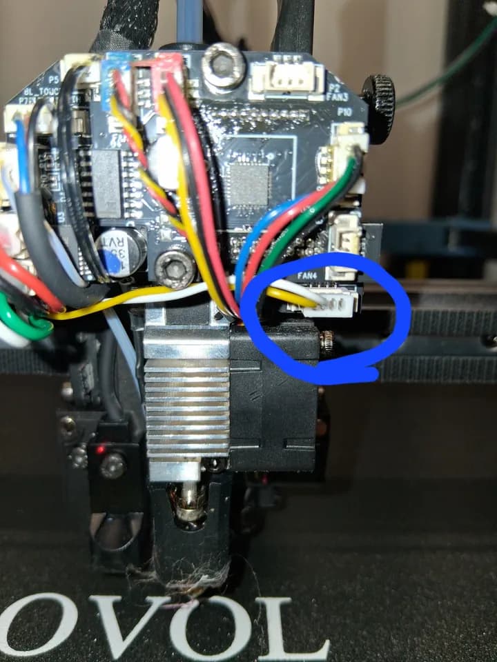
I connected the motion/tangle sensor to the PA9 pin on the toolhead and runout to the stock port on the mainboard. Then I added the following code to my printer.cfg
[filament_motion_sensor encoder_sensor]
switch_pin: ^!extra_mcu:PA9 # motion sensor IO is ^!extra_mcu:PA9
detection_length: 4.88 # accuracy of motion sensor 2.88mm
extruder: extruder
pause_on_runout: True
runout_gcode:
#PAUSE # [pause_resume] is required in printer.cfg
M117 Filament encoder runout
insert_gcode:
M117 Filament encoder inserted
You will need to change the plug over to a jst 1.25mm
Black = Yellow
Green = White
Now both sensors work as intended.
Well done. I assumed you’d not want to add wires to the umbilical so only researched pin availability on the mainboard.
I hope you used “high flex” wire.
Just used the wire that came with the sensor, no issues so far.
Thank you, Good Sir! Have referenced your solution in the bracket for the SFSv2 on Printables:
Good deal, I have also placed this info on all related files I have found on printables. I had tried the other methods and just could not live with only using half of the BTT sensor I had purchased.
I am unclear as to how to connect to the pa ( pin on the main bord. do you just use the existing wires?
Hi, I am using the BTT SFS V2 on my SV08. Due to the fact that I am also running the BTT Eddy Duo I connected the SFS switch to the old runout sensor switch Pin and the SFS encoder to the old pressure switch Pin. Some changes in the printer.cfg; works great.
Hi, which pressure switch pin do you mean? Can you provide your printer.cfg changes for your solution please?
Thanks!
The standard runout sensor is connected to Pin PE9 and the standard pressure switch to PE12.
The BTT SFS V2 needs 4 wires: VCC / GND and two switch Pins; one for the runout switch and one for the encoder switch. So I took the old runout switch Pin and took the pressure Pin PE12. Connect these wires (double check with Multimeter) to the BTT SFS and adjust the printer.cfg:
[filament_switch_sensor filament_sensor]
pause_on_runout: True
runout_gcode:
  # G1 E10 F1500
  # G1 E-100 F1500
  M117 Filament switch runout
insert_gcode:
  M117 Filament switch inserted
event_delay: 3.0
pause_delay: 0.5
debounce_delay: 1.0
switch_pin: ^PE9

[filament_motion_sensor encoder_sensor]
detection_length: 3.0
extruder: extruder
switch_pin: ^PE12
pause_on_runout: True
runout_gcode:
  M117 Filament encoder runout
insert_gcode:
  M117 Filament encoder inserted
event_delay: 3.0
pause_delay: 0.5
This works for me perfect.
Thank you!
I will check it when i’ve got the sensor.
Can you share how you wired the sensor to the two pins?
See my post above. The BTT SFS V2 needs 4 wires: Vcc / GND and two switch Pins. So if you just want to change the original Runout Sensor you can take that port with Vcc and GND and one Sensor Pin; either runout or encoder. Or you do it like I wrote above.