I have been trying to do some skew corrections with the Vector3D Califlower V2. And now I’d like to doe the adjustements in Klipper, but according to Skew correction - Klipper documentation there should be [skew_correction] in the printer.cfg. So now I am unsure how to proceed, anyone got an idea how to?
I could understand that on a bigger printer, but the Zero..??
Well it may not be necessary, but it seems to be the biggest deviation XY. So if it is possible I’d like to correct it.
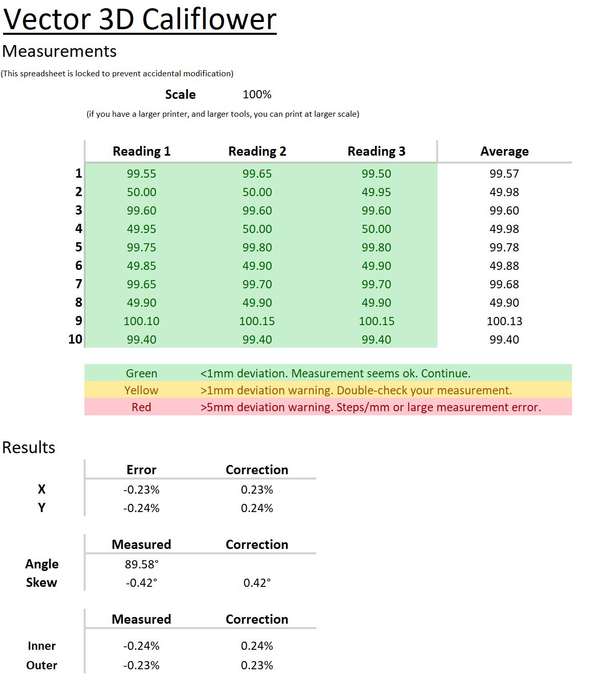
Your measured “error” is symmetric for X and Y. You have no skew.
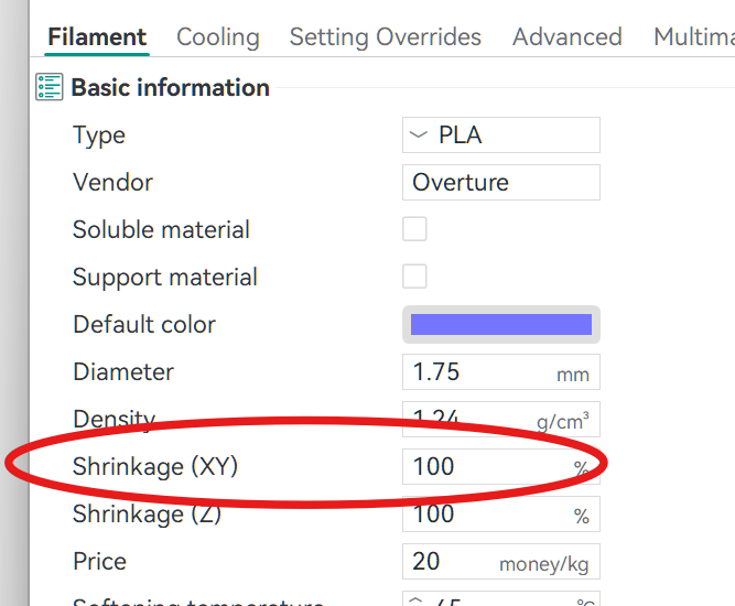
0.23% is most likely shrinkage. I’d recommend you leave Klipper as is and use the shrinkage compensation function in your slicer.
Skew correction is built into Klipper see:
1 Like
Unfortunately, the SET_SKEW command is not available in Sovol’s stripped down Klipper, so there’s really nothing that can be done for skew, unless its so bad you’re willing to adjust your steps/mm (mine wasn’t so I just settled for just the higher accuracy shrinkage that’s baked into the CaliFlower/CaliLantern approach).
Once an empty [skew_compensation] is in your printer.cfg, the SET_SKEW commands run without error (I could have sworn I had already added that, sorry…)
So now I’ll print a 2nd CaliLantern and see if it actually improves
I don’t understand how the data shown in the spreadsheet above can be used to calculate skew.
Skew is when a square prints as a parallelogram. It shows when the diagonals of a square are unequal. The spreadsheet you screenshot should then have different results for X any Y.
I’d use this YACS (Yet Another Calibration Square by Paciente8159 - Thingiverse to verify skew (and correction factors)
Keep us posted on your results.
Vector 3D’s CaliFlower was popularized by CNC Kitchen’s video on the topic. In particular the 10 different measurements should clarify how its makes the calculations. Yes, it is a small purchase, but I think the spreadsheet, online calculator, and thorough instructions make it well worth it.
I use the similar CaliLatern (which also tests the Z axis), scaled up to 135% to maximize the Zero’s print volume and I get:
- Size
- X -0.24%
- Y -0.38%
- Skew
- XY -0.266°
- ZX +0.055°
- ZY -0.001°
- Extrusion
- Inner -0.05%
- Outer -0.57%
- Shrinkage
- 99.69% (PLA)
It is the difference between the diagonals measured form 9 to 9 and 10 to 10, that determines the skew.
As @rpcyan mentioned adding an empty [skew_compensation] in printer.cfg is enought ot enable it. Funnily enough it was mentioned in the CaliFlower instructions. But I thought there would be more to it.
So anyway I ran it again after adjusting XY compensation (because why not) for the used PETG and adjusting the skew in klipper I sliced and reprinted it. Happy with the results now.
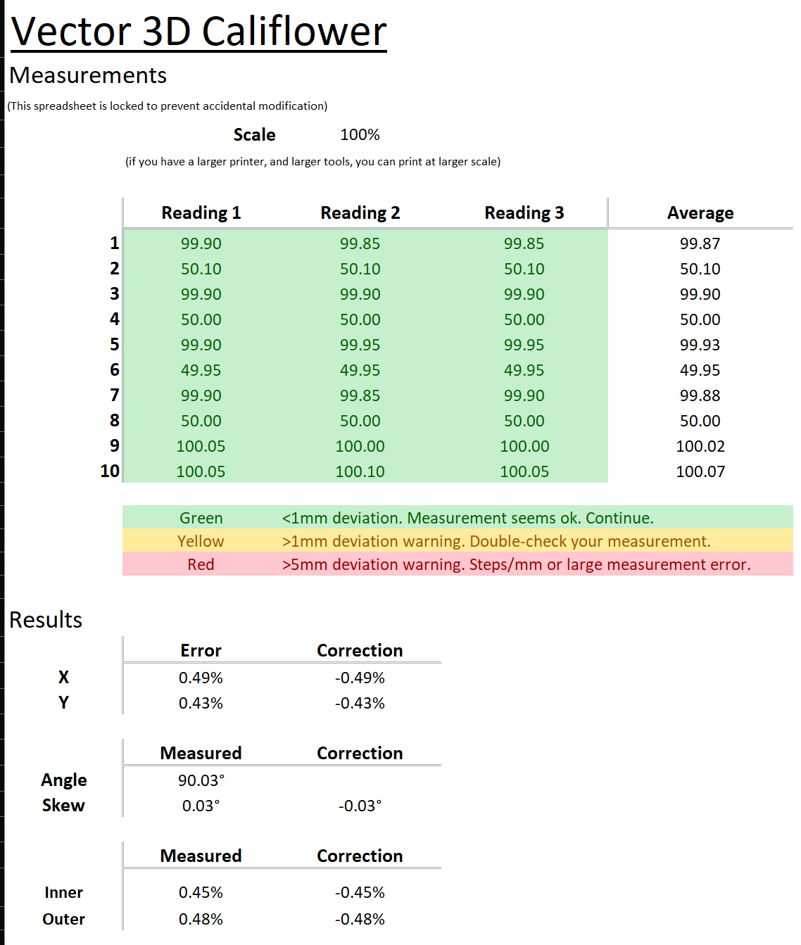
From 0,42 degrees to 0,03 degrees (that’s way with in the margin of error of my measurements).
Kind off weird XY values are closer to the target 50 and 100mm, but show bigger deviation. Than before. Now 0,43/0,49% what was 0.23/0.24% before. But I am not worried about that.
When viewed from the top, the belt path of the Zero is not completely parallel to the (x-axis) aluminium extrusion. Instead the belt is at an angle with the (x-axis) aluminium extrusion, basically creating a triangle (one the left and one right side of the toolhead) with the (x-axis) extrusion being the adjacent side and the toolhead being the opposite side.
Throughout the x-axis travel, the angles of both triangles change, so there might be some change in the geraing for the x-axis - and because of the core-xy some change in the y-axis gearing too.
I’m not to sure with the following, but this might affect the skew correction test.
One might redesign the toolhead attachment of the belt, to make it parallel to the x-axis extrusion.
I agree, the belt misalignment will affect the skew and xy positioning. On one hand it bothers me as it basically is a design error, on the other hand I don’t feel like fixing it haha.